Monday, April 30, 2012

uLab 28 PIC


PROJECT OBJECTIVE: A PIC 28 pin processor board for use with slbb's. The board plugs into the slbb and incorporates an adjustable regulator for 5Vand 3.3V, a serial communication connector, ICSP, Picaxe and BasicAtom interfaces.

INTRODUCTION: This device was developed to expedite the setup of projects on a solderless breadboards for 28 pin PIC processors including Picaxe and BasicAtom.

Power: A single adjustable LDO regulator provides 5V and 3.3V jumper selectable, switchable power. The switch in its off position shorts the circuitry to ground for a clean shutdown. A green LED indicates power on.

Programming: The processor can be programmed in-circuit using the Tiny bootloader with the communication port or ICSP . When using the ICSP, the programmer, such as the PicKit2, should not be used to power the processor because of the shorting switch. If a Picaxe or BasicAtom part is being used, then programming is by the appropriate comm connector.

Communication: The communication interface is not provided on-board, but requires and appropriate breakout device for RS232 or USB to TTL conversion. A RS232 SMD breakout board is included as one of our projects, with pcb and kit available for those using PC com ports. The FTDI USB to TTL cable available from Mouser will work with Tiny bootloader which requires RTS on pin 6 for auto-bootloading. (We believe that Amicus requires DTR on pin 6.)

Testing: A single red LED is provided for quick setup testing. A single momentary switch is also provided.

FEATURES:
  • Header for plugging the I/O ports to a slbb
  • Each port pin marked to ease jumper connection
  • Mating pins to the slbb power busses
  • 3.3V and 5V selectable power with switch
  • Picaxe 28X and BasicAtom Nano programming ports
  • 28 pin PIC processors: 16F886, 18F2420, 18F25K20, 18F25K22, etc with Tiny bootloader
  • Power LED
  • Single LED tied to B0 and switch to B1 for testing
  • Connector bank for easy connection of sensors to ADC's

DIMENSIONS:
2 inch by 3 inches

SCHEMATIC DIAGRAM:


PICTURE:


BOM:

Count Label-Value Designation(s) Mouser PN Manf


1 470uf 25V C1 UHE1E471MPD Nichicon
1 22uf@16V C2 UVR1C220MDD Nichicon
2
C10 C9

1 .1uf C3 C4 C5 C8 C11 C12 C322C104K5RSTA Kemet
2 22pf C6 C7 140-50N2-220J-RC Xicon
1 1N5817 D1 1N5817 Fairchild
1 LED T1 GRN D2 HLMP1790 Everlight
1 BAT85 D3 BAT85 Vishay
1 LED T1 RED D4 HLMP1700 Everlight
1 1N4148 D5 1N4148 Fairchild
4 HEADS6 J1 J2 J3 J8
3M
1 HEADS24 J4
3M
1 HEADRAS6 J5 J6
3M
1 620454-3 J7 640456-3 AMP
1 FHEADS2 JC1
3M
5 HEADS2 JP1 JP2 JP4 JP5 JP6
3M
1 HEADS3 JP3
3M
1 PJ102A P1 CP-102A-ND Cui (Digikey)
5 10K R1 R10 R2 R6 R9 270-10K-RC Xicon
1 360R 1% R11 299-360-RC Xicon
1 432R 1% R12 299-432-RC Xicon
1 120R 1% R13 299-120-RC Xicon
1 22k R3 270-22K-RC Xicon
2 1K5 R4 R8 270-1.5K-RC Xicon
1 470R R5 270-470-RC Xicon
1 180R R7 270-180-RC Xicon
1 Switch Slide S1 103-12100-EV Mountain Switch
1 SW 3.5x6mm RED S2 TS4311T2601-EV Mountain Switch
1 SW 3.5x6mm BLK S3 TS4311T1601-EV Mountain Switch
1 Pic 18F U1 18F25K22I/SP Microchip
1 Reg. LDO Adj U2 NCP1117DTA ON Semi
1 XTAL 16mhz Y1 16 mhz
1 Dip Socket 28 pin SK1 4828-3004-CP 3M


PCB LAYOUT: (if required)

Wednesday, April 25, 2012

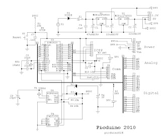
Picduino, Pic on the Arduino Form Factor


PROJECT OBJECTIVE: Replace the AVR processor on the Arduino form factor with a 28 pin 18F PIC processor. Add both an EEPROM and RTC to the design. Use thru hole, including DIP parts, to facilitate assemble.

FEATURES:
  • 18F, 28 pin PIC processor (16F optional)
  • Tiny bootloader with auto-bootloading (DS30 coming)
  • Arduino pcb form factor
  • Serial communication using breakout boards
  • Stackable connectors with Arduino compatible pinout
  • Dual LDO regulators for 3.3V and 5V.
  • Power switch, 300ma
  • Jumper for comm port power
  • Onboard I2C RTC and EEPROM
  • ICSP connector at front
  • Reset switch accessible at front
  • Testing LED on B0 at front

INTRODUCTION: Initially, the18F2520 will be used since there is an available Tiny bootloader that we have been using with good results. Presently, we are testing the 18F25K22 with the DS30 bootloader.

This design uses the Arduino physical stacking connectors, without change, except for some signal assignments. The USB circuit which is incorporated on the Arduino has not been incorporated on the Picduino, but will be contained on a breakout board allowing both RS232 and USB serial communication. The RS232 breakout will be available with the initial project and for USB communication the Sparkfun DEV 09716 will be used. This will provide the same USB functionality as the Arduino with the exception of powering the Picduino from the USB port.

The 18F2520, 18F25K22 and 18F25K20 use 5V and 3.3V respectively; therefore, dual LDO regulators have been provided. Dual regulators, also seem reasonable, since there may be shields requiring both voltages. A switch is used to apply power to the board.

Since the intended use for the Picduino is as a base unit for the Rainwater Level Monitor project, an RTC and EEPROM were incorporated on the main Picduino PCB. Because the Picduino can operate at 3.3V the RTC, DS1307 can't be used and has been replaced by the PCF8563 in the design

For software development, several compilers can be used including: OS Basic, MikroBasic Pro, Swordfish and Proton. If you use the 18F25K20 or 18F25K22, then the free Amicus compiler can be used. With the latest updates, PicKit2 will program the 18F25K22, see Tips and Tricks. The18F25K22 is also supported by MPLAB.

The “C” compiler used by Arduino can create compiled modules and then linked from libraries using an Include directive. Both MBP and SF can do this, but PicBasic Pro, Proton Basic, OS Basic and Amicus can't. This feature of the AVR-GCC compiler is one of the reasons that the AVR processor was picked for Arduino and why the Arduino platform is so successful. Our intention is to develop code with Swordfish and OS Basic.  

As an aside, the method of Arduino development is similar to our method described in this site. Compile the code, download it, examine its behavior, then make adjustments to the code and try again. There are code developers out there who use the AVR-GCC to create modules that the uninitiated can use. Most of the hard work is done by those developers. For example, writing code to generate the model train DCC signal is not simple because of the timings involved, but I am sure some developer is out there building a DCC module.

Note 1: The Arduino uses DTR of RS232 to reset the processor for an autoboot. The FTDI cable brings out RTS on pin 6 not DTR so it will not work in autoboot mode. Sparkfun sells a USB breakout board that will work (DEV-09716).


DIMENSIONS:
W: 2.7 in, L: 1.9 in, H: .5 in

SCHEMATIC DIAGRAM:


PICTURE:

Picduino without serial breakout


BILL of MATERIALS:

PCB LAYOUT:

Monday, April 23, 2012

Using a LCD Terminal for MCU Software Debugging

One of the advantages of an in circuit debugger, ICD, is the ability to monitor variables. If you are using a bootloader for development an LCD terminal can be used for that purpose. Connect the LCD terminal to an unused pin on the MCU and output the variable information using software UART code that most compilers provide. Setting a break or tight loop right after the variable output is often necessary. In time I will provide some examples of this method below.

Sunday, April 22, 2012

LCD Terminal, the GMterm II


Project GMterm II

PROJECT OBJECTIVE: To develop a serial LCD terminal written in OS Basic that will respond to the PH Anderson command set. To design a pcb for the project.

INTRODUCTION: This project started out as an attempt to produce firmware for the 16F886 that would respond to the command set of the PH Anderson serial LCD products sold as programmed 16F628 chips, except with all code written in Basic.. Andersons code was written in assembly language, used an interrupt driven buffer on the serial input and provided RS232 and TTL inputs. As mentioned elsewhere in this site, I used PHA's device to monitor variables during code development and .now I use the GMterm 2.

GMterm has all code written in OS Basic and responds to all of the PHA's commands, except for big numbers. It uses a interrupt driven barrel buffer for the input serial data stream. A pcb has also been designed to house the GMterm chip and, though, the initial design used the 16F886, the pcb can also use the 18F2420, 18F2520 and the 18F25K22. Since the code is written in Basic, conversion to the other MCU's is easy.

Since the 28 pin devices have additional I/O, other capabilities could be added to the PHA design, such as, four selectable baude rates, command controllable contrast and serial interface daughter boards.

FEATURES:
  • LCD: 1x8  to  4x40
  • Backlight control, PWM
  • Contrast control: digital or analog potentiometer.
  • I/O, direct TTL and RS232
  • Daughter board for RS232, RS485 ( full and half duplex) and USB
  • I2C with branch, 16 address, 6 meters max.( not implemented)
  • USART select: 8 or 9 bit
  • baude: 2400, 9600, 19.2k, 38.4k
  • GPIO
  • Command Set: Basic and extended
  • Tiny Bootloader
  • MCU: 16F886, 18F2420, 18F2520 and 18F25K22
  • Requires external regulated power.

DIMENSIONS:
W 1.5 inch, L 2.8 inch

PICTURE:


SCHEMATIC:


SLBB DEVELOPMENT SETUP:
Intro: The solderless breadboard, slbb,  setup uses the uLab28 PIC and is pictured below. This setup implements part of the circuit diagram: 16F886, LCD, contrast pot and a speaker. If you do not have a uLab28 then the entire circuit can be wired on the slbb. You will also need to provide +5V to the circuit from a separate power supply or a regulator wired on the slbb.


Development setup for LCD terminal using uLab28.


What's Needed
  1.  SLBB with 830  or 1660 contacts
  2.  Wart: 6 VDC @ 500ma unregulated
  3.  Addon: PWR-1 or (7805 + parts)
  4.  Addon:RS232 ( ST232CN + parts)
  5.  Microchip 16F886 with Tiny bootloader
  6.  20x4 LCD Vishay L020N4AYYHET or equivalent
  7.  Digital Pot.CAT5113LI-10-G
  8.  Oshonsoft PicSimIde Basic compiler
  9.  Tiny Bootloader
  10.  PC with a RS232 port

The LCD used in our setup has a SIP connector at the top of the display similar to the Vishay part above. The sip can be plugged directly into the slbb or use adapters with a ribbon cable. The Simple Menu project uses adapters.

If a 7805 regulator will be used in your setup, then a 7.5VDC wart may be needed. This can be determined by checking the voltage drop across the regulator. The backlight on the LCD draws the greater power, about 200ma. If you are having overheating, change the backlighting level or turn it off.

Step 1) Wire a basic setup including: processor and RS232 interface. Connect a LED with resistor from B0 to ground. The uLab28-PIC has all of this on-board.
Step2) Compile a LED blink routine and download to make sure bootloader and hardware are working properly. There is a blink routine in zip file.
Step3) Complete basic SLCD wiring while referring to Basic circuit diagram. See zip file.


PDF DATASHEETS:

LINKS:
Tiny Bootloader
Oshonsoft

LISTING:


PCB LAYOUT:


Friday, April 20, 2012

Rain Water Tank Level Monitor

This a work in progress.

Design Spec: To measure rainwater tank water level in a single tank. Two different measurement methods will be incorporated: pressure and sonic ranging. The data will be shown in height and volume. Using a battery backup realtime clock, data will be logged twice daily over the period of one year. An RS232 port will allow the data to be downloaded to a  computer for analysis. A large character LCD will provide continuous display of time and water level.

Components
1) Two different RTC's are being tried: DS1307 and PCF8563.
2) A 24LC512 for memory storage.
3) PIC18F2520 with Tiny bootloader
4) 16x2 or 20x2 LCD: Vishay 016N002L or 020N002L

Software
1) Basic Clock: Simple realtime clock using a RTC I2C chip. 12/24 function is included. Start time is set as part of the code.

                a) Clock_DS1307_LCD_2.bas
                b) Clock_PCF8563_LCD_2.bas

2) Menu Routine: This menu routine uses 3 buttons: Select, Up, Dwn. The menu items are shown on the bottom line of the display. Execution occurs on the leading edge of button press and, following execution, waits for the button to be released. The buttons are connected to the port pins with a 10K pullup.

                Clock_menu_4.bas              This code is not complete.

3) Clock with Menu:

In Process. Code written to date can be found here in files. RTC_clock.zip

Notes 1)  The code is written using Oshonsoft Basic for the 18F2520. From this point on I wish to switch to the 18F25K22 and use either the Swordfish (preferred) or the Amicus (Proton) Basic compiler. The Swordfish would be preferred since it uses a linking loader, so that modules can be developed much like the Arduino. Unhappily OS Basic does not as yet support the 18F25K22.


Rain Water Monitor Shield Prototype.

Wednesday, April 18, 2012

DS30 Bootloader for the 18F25K22

I have been using the Tiny bootloader for my Pic projects, but have decided to change to the DS30 bootloader mainly because of its ease of use and extensive device set.

More to come.

ZIF Adapter for PicKit2

I have an older Melabs serial pin programmer which I purchased with a ZIF adapter. Though the Pic processors can be programmed in situ using the ICSP connect, if it is available, during development I find it is easiest to use a ZIF socket. To that purpose a ZIF adapter has been designed for use with the PicKit2. The ZIF adapter plugs into the PicKit2 ICSP connector and a switch on the ZIF board changes Pic number of pins, i.e., 28/40 or 20 etc.


At the moment I do not stock this board, but it is available from Batchpcb. The ZIF socket is available from several sources as well as the switch.

BOM:

  1. PCB: Batchpcb, ZIF PicKit2 Adapter
  2. ZIF Socket: Futurlec, universal 40 pin ZIF socket, ZIFU40
  3. Switch: Mouser, Slide Switch